
Monitoring Parallel Cables
Parallel cables effectively refers to two or more cables which share a common phase running from a source of power to a load/loads.
In the below example we look at the blue phase from 2 x 3 phase inverters. Note: the same principle applies to red and white phases, as well as paralleled incoming grid cables.
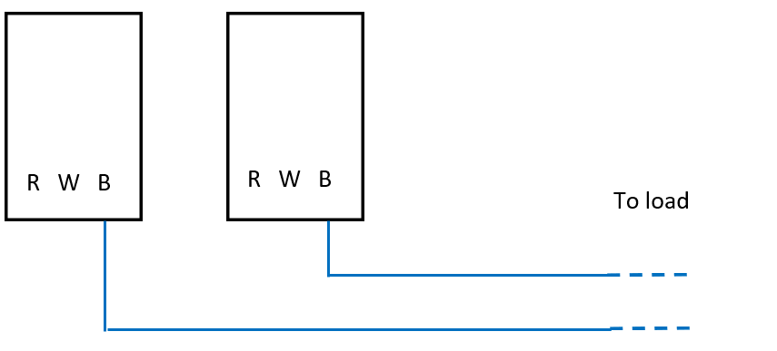
There are two options here:
-
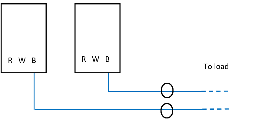
Use 2 x CTs such that the blue phase from each inverter is monitored by a separate CT:
-
Use 1 x CT such that the blue phase from each inverter is monitored by a single CT
(this is only possible as they share the same phase):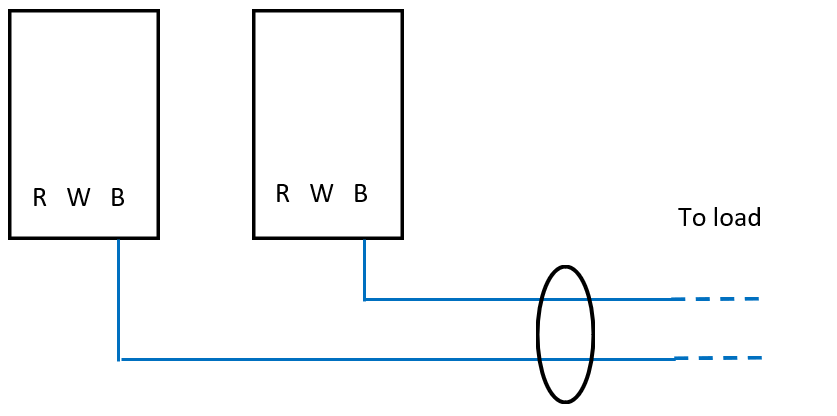
It is important to note the following:
-
There is a monitoring benefit to using separate CTs for inverters, as we will produce a zero gen alert if one of the inverters drop out. If one CT was used to measure both inverters we would still record a current in the event one of the inverters stopped producing.
-
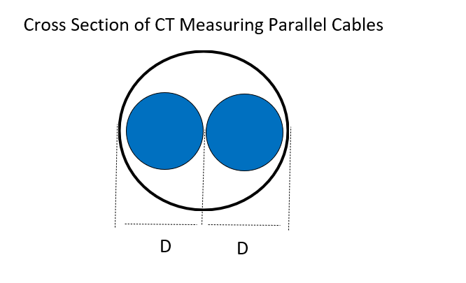
If one CT is used to monitor multiple parallel cables it needs to be appropriately sized that it can handle the max current from both sources and can also fit comfortably around both cables. This means CT diameter needs to be at least as big the combined diameter of electrical cables. Example shown below for two equal sized blue phase cables with diameter D :