

iStore 1P commissioning
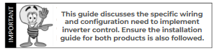
- Important
CATCH Control hardware is used as a substitute consumption meter for compatible inverters and includes a range of additional features including inverter, battery and load control via our advanced hardware and software.
Our hardware and software can be connected and used in a variety of ways, so it is vital that you understand these instructions.
Please read these important details before commissioning:
- CATCH Control must only be installed by licensed electricians
- This manual is inverter specific and must be read in conjunction with the 2CH or 6CH Installation Guide and the brand specific inverter installation guide.
- Ensure you follow the commissioning steps described in the correct order
- CATCH Control can be used to manage and control multiple inverter brands on a single site. Please refer to each brand specific guide.
- CATCH Control CT’s must measure inverter production and site consumption for full functionality in most Modbus 485 RTU applications.
- In some Modbus TCP/Sunspec applications, solar production measurement is not required.
- Multiple CATCH Controls/inverters can be connected via WiFi Cloud Tethering where required.
- In Modbus TCP/Sunspec applications, all CATCH Control hardware must be connected to the same local network
- CT’s can be extended up to a maximum of 10M and will require a 120 Ohm terminating resistor in such applications.
- All CATCH Control hardware must be WiFi connected to enable full functionality, support and warranty and Bluetooth connected for commissioning
- Each inverter brand has specific commissioning requirements and operational characteristics described in this guide. Please refer to the following brand specific characteristics
Please check our latest compatibility and CSIP compliance here
About our apps and software
We provide a variety of different software applications serving different purposes and in some cases with different features.
- Our Monocle and Configurator apps are suitable for mobile devices (smartphones and tablets) only
- Our MyFleet and Solar Analytics apps can be used on mobile or desktop
- It is critical that you download and create a Configurator “Installer Account” FIRST before any other accounts
- The same login is then used for Configurator and Monocle (and MyFleet?)
- All CATCH Control sites are automatically replicated and created in Solar Analytics for the owner.
- An Analytics Fleet account can also be created (if preferred) ensuring all sites go into a single fleet for you. Please contact us to set this up.
It is critical that mobile devices are operating on the latest software to ensure our apps operate correctly.
2. iStore Characteristics
The following characteristics uniquely apply to iStore 1P inverters installed with CATCH Control hardware:
- Applies to iStore models IS-HYB-XXXX-1PH Check CEC and CSIP lists here.
- iStore inverters are connected to CATCH Control via Modbus 485 RTU
- You will need to set up the control functionality for export limitation in both the iStore app and the Configurator app
- In non-battery applications the iStore WiFi dongle is not required
- Ongoing monitoring, reporting and adjustment is managed via the Monocle app. The iStore app cannot be used for advanced controls and may report incorrectly.
- CATCH Control is approved for CSIP/Backstop/Dynamic control
- CATCH Control is not configured for master/slave configurations
- CATCH Control is not configured for hybrid battery configurations
- Native inverter monitoring will not report correctly when using CATCH Control
3. Inverter control wiring
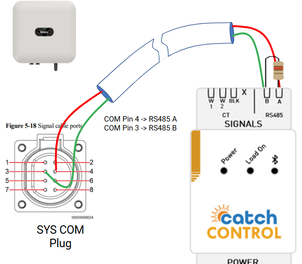
iStore inverters are connected to CATCH Control via RS485 RTU hardware connection.
Ensure that:
- Connection is on accordance with the diagram below
- The data cable is rated for the voltages it will be in close proximity to.
- A 120 Ohm terminating resistor may be required at the CATCH Control terminals if the cable run is longer than 10m.
4. CT & Power wiring
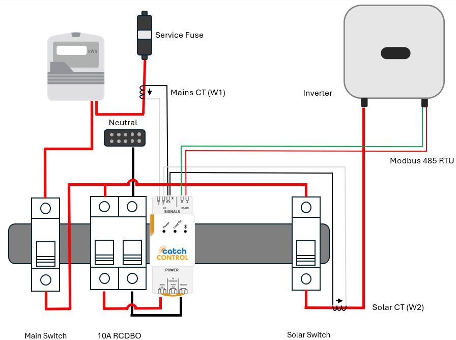
Please refer to the CATCH Control 2CH Installation guide for detailed wiring and connection information.
This diagram describes the typical wiring and CT placement.
Note:
- The mains CT should be fitted to W1 and the solar CT should be fitted to W2. The black CT wire is common.
- If a backup circuit is used, pass the backup cable through the solar CT W2 in parallel with the solar cable
- Connect 230V AC power via a suitable 10A RCBO to the Active IN and Neutral terminals on the base of the unit.
5 About configuration
Configuring CATCH Control to operate correctly requires the appropriate settings in
the relevant inverter app and the CATCH Power apps (Configurator and Monocle).
You will need all the relevant apps downloaded and you will need to be a registered user to proceed.
This section describes the steps in configuration and must be completed in the correct order once the inverter and CATCH Control hardware is installed.
This Basic configuration enables CATCH Control as the consumption meter and enables static export limits. See Advanced configuration for flexible, dynamic, ev or wholesale market control.
6. CATCH Configurator app settings
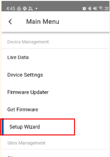
- Log into the CATCH Configurator and run the Wizard.
- Complete steps 1-5 using the Wizard
- Before proceeding to Step 6 switch to the HiSolar app.
7 HiSolar app
Follow the iStore commissioning process as outline in the IS-HYB-1PH User Guide. Once the inverter is setup, follow these steps.
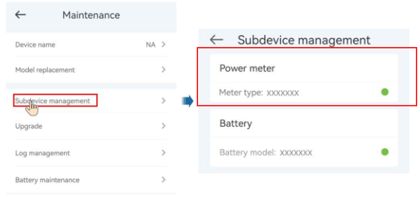
- On the home screen choose Maintenance > Subdevice management > Power Meter
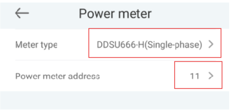
- Ensure meter DDSU666-H is chosen and power meter address is 11
- Then press the SUBMIT button.
- It is critical to now set the inverter to Zero Export which enables CATCH to take control of the inverter for Backstop, Dynamic, EV integration and wholesale market access.
- On the home screen choose Power adjustment > Grid-tied point control > Active Power
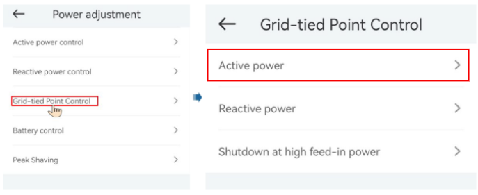
- Set the export limit to ZERO, and the other settings as shown
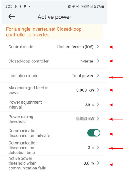
Once these steps are complete, return the the Configurator app.
8. CATCH Configurator app settings
- Continue from Step 1 where you left off and choose I-STORE-1P
- You should see 3 green ticks indicating success
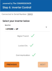
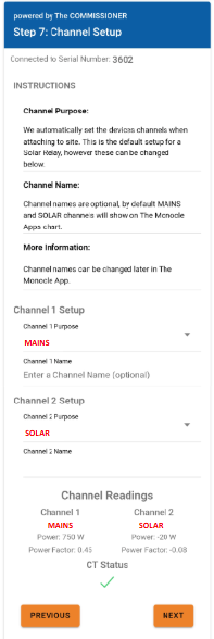
- Continue to step 7 of the Wizard and complete the CT configuration as shown with CH1 (W1) set as MAINS and CH2 (W2) is set as SOLAR.
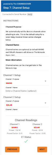
- Continue to step 8 and enable EDDE control.
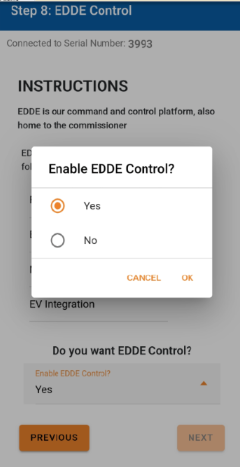
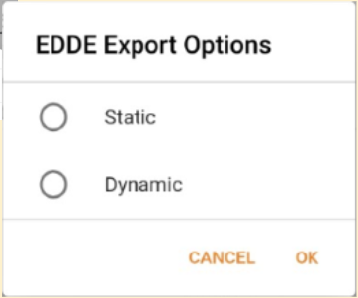
- You will then be asked to define how the site is to be managed, static or dynamic.
-
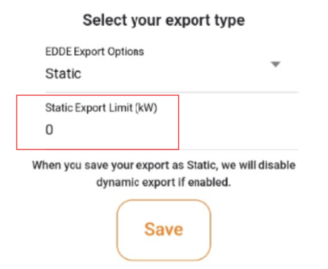
- Static: Is when the DNSP tells you there is a fixed export limit. Example the connection application might say the site is limited to 5kW. This is a static export limit.
- If the site is Static limited, enter the Static Export Limit (kW) in the appropriate field
-
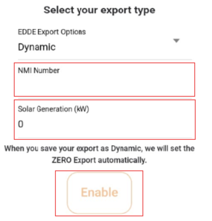
- Dynamic: When you put the connection application in you would have nominated for the dynamic or emergency backstop connection (Vic). The DNSP will adjust the export limit based on emergency or daily requirements. You will need the NMI to complete the dynamic connection setup.
- If the site is Dynamic or Backstop (Vic) limited, enter the customer’s 10 or 11 digit NMI. Then enter the total AC solar capacity of the site (including any old systems)
- Then press Enable
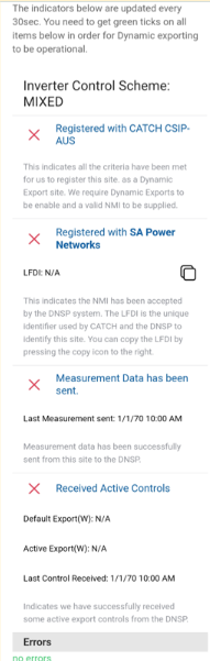
- Once enabled, you will see the following screen showing you how the registration is progressing. Green ticks indicate that the system has been successfully tested, is communicating and registered with the DNSP.
- Once complete, do one final review of the configuration and press save.

9. Multi Inverter Installations
When using CATCH Control for multiple iStore inverter installations you need to treat them all as there own individual installation.
Do not use the i-Store multi inverter solution.
The diagram below shows how to connect the inverters so they will automatically work together
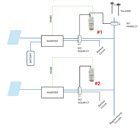
The set up multi inverter configurations is slightly different.
- For Inverter 1, set up as standard.
- For inverter 2, instead of setting Channel 1( W1) as MAINS and Channel 2 (W2) as SOLAR simply set Channel 1 & 2 as OTHER
10. Completion and support
The configuration should now be operating correctly and the site is ready for use.
-
The Commissioner Wizard will notify you if things look abnormal.
-
Ensure you provide the Owners Guide to system owners so they understand how to adjust the site settings if required
-
Ensure you provide a link to the Wifi reconnection guide so owners can reconnect if wifi drops out.
-
To configure unique settings for load control, EVSE control or market price control please refer to our detailed service specific guides.
-
Owners written guide to the Monocle
Support
Please contact our tech support team on (02) 5700 5717 for assistance on set-up or commissioning.
CATCH Power
180 Dumaresq Street Glen Innes NSW 2370 Australia
Ph: +64 2 5700 5717