

CATCH Control 6CH Installation Manual
Introduction
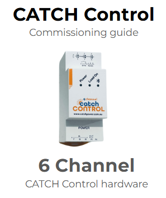
Section titled “Introduction”CATCH Control hardware is used as a substitute consumption meter for compatible inverters and includes a range of additional features including inverter, battery and load control via our advanced hardware and software.
Our hardware and software can be connected and used in a variety of ways, so it is vital that you understand these instructions.
Please read these important details before commissioning:
Section titled “Please read these important details before commissioning:”- CATCH Control must only be installed by licensed electricians
- This manual is specific to the 6 Channel CATCH Control and must be read in conjunction with brand specific inverter installation guides.
- Ensure you follow the commissioning steps described in the correct order
- CATCH Control can be used to manage and control multiple inverter brands on a single site. Please refer to each brand specific guide.
- CATCH Control CT’s must measure inverter production and site consumption for full functionality in most Modbus 485 RTU applications.
- In some Modbus TCP/Sunspec applications, solar production measurement is not required. Please refer to each brand specific guide
- In Modbus TCP/Sunspec applications, all CATCH Control hardware must be connected to the same local network
- Multiple CATCH Controls/inverters can be connected via WiFi Cloud Tethering where required.
- CT’s can be extended up to a maximum of 10M and will require a 120 Ohm terminating resistor in such applications.
- All CATCH Control hardware must be WiFi connected to enable full functionality, support and warranty and Bluetooth connected for commissioning
Before Getting to Site
Section titled “Before Getting to Site”You will need the CATCH Configurator app and CATCH Monocle apps installed and registered to commission our hardware.
To register, modify or troubleshoot the CATCH Configurator or CATCH Monocle app refer to this guide.
6 Channel CATCH Control introduction
Section titled “6 Channel CATCH Control introduction”The 6 Channel CATCH Control has a number of unique features and capabilities.
- Suitable for use on 1 Phase, 2 Phase or 3 Phase sites
- Includes 6 CT channels that can all be configured to measure different things
- Includes a 240V AC Output designed to drive a contactor.
- Includes a dry contact output designed to control a small relay coil or be connected to a set of DRM terminals
- When talking about multi phase electrical installations electricians are used to using Red/White/Blue or Phase 1/2/3 for referencing the different phases. WE DO NOT USE THAT TERMINOLOGY. All through this document you will see references to Phase R/S/T,
and that is how we refer to the different phases. It is the same thing as what you would typically be used to but it’s just a little more
relevant in an international setting. - Phase rotation: The following sections describe which phase should be connected to the R/S/T power input terminals. This can be modified, but we strongly recommend you stick to the standard configurations.
- Phase Matching: IT IS ESSENTIAL to ensure that the CTs that are measuring current are on the correct phases and mapped correctly.
1 Installing the hardware
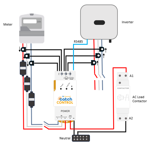
Hardware installation is broken down into the following steps:
- Power connection - Connecting CATCH Control power input wiring
- CT Connection - Connect and phase matching CTs
- Inverter Connection – Connecting an inverter
- Load Connection – Connecting a load via the AC Out port and ann AC contactor
- DRM connection - Connecting an Air Conditioner or DC Coil relay via the DRM port
1.1 Power connection
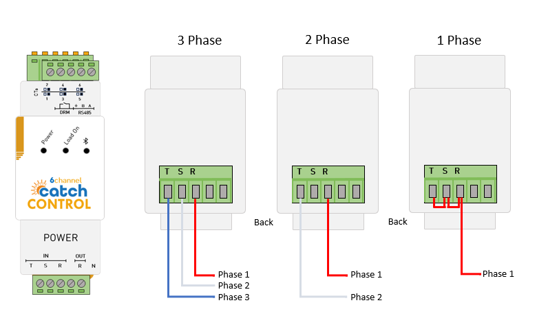
Install the CATCH Control and connect the Power as shown in the diagram below to the “In” terminals.
Carefully note the different input wiring depending on whether you are using 1 Phase, Split Phase or 3 Phase. The Neutral connection is common for both the power “In” and power “Out” terminals.
1.2 CT Connection
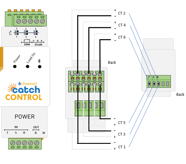
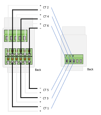
By default, the CT’s are matched to the power “In” terminals and it is very important that you match the correct CT channels to suit the Phase configuration you are using. See the diagram below showing our standard CT mapping.
- Only use compatible CT’s supplied by CATCH Power
- The CT’s should ALWAYS be placed on the active wire, never the neutral.
- Always terminate the CT into the device BEFORE clamping it around the wire
- Make sure the arrow on your CT is pointing in the same direction as the arrows in the circuit diagram
- The white CT wires are positive and CT black CT wires are negative.
- The stripped end of the CT wires precut to suit the connector Do not cut, solder them or fold. Push down on the terminal latch and insert the wire fully, ensuring there is no exposed conductor.
- Matching the CTs to the correct phase is essential
NOTE : If your main consumption meter is remote from the inverter, you can install multiple CATCH Control devices and wirelessly connect them to enable full wireless control via our “Cloud Tethering” feature. Refer to our Cloud Tethering guide here.
1.3 Inverter connection
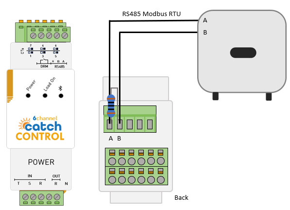
The majority of inverters CATCH Power controls are connected via hardwired RS485 RTU cable. The following diagram shows the generic 485 connection.
- Use CAT6 or equivalent cable. The voltage rating needs to be 600V or better as it is being run through the switchboard.
- Use a twisted pair as the A and B conductors (ie Blue and Blue Stripe)
- Keep the cable away from large current carrying conductors if possible.
- For runs longer than 10m terminate the Solar Relay end with the 200 Ohm resistor supplied in the box.
- If you are controlling multiple inverters on the same site you will (generally) need multiple CATCH Controls communicating via RS485 to each inverter, and will need to commision and set up each inverter separately.
Please refer to the individual Inverter Guide for unique connections and commissioning for each brand.
Please also note that SMA, Fronius and Fimer inverters can be connected via RS485 TCP which does not require a hardware RTU connection.
1.4 Load Connection
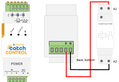
CATCH Power’s 6CH hardware includes the ability to drive an optional AC contactor to turn loads on or off. The following diagram shows the generic connection.
- NEVER attempt to drive a load directly from CATCH Control hardware
- Choose a suitably (load) rated 230V AC Contactor which is Normally closed. We recommend Contactors with a bypass switch.
- You can use more than one Contactor but can only set one schedule (ie they will behave the same)
- Connect the “Out” R (Active) terminal from the CATCH Control to either A1 or A2 on the contactor, and connect the Neutral to the neutral terminals.
1.5 DRM Connection
The DRM terminals are a solid state relay (SSR) giving a dry contact used for control of a load.
The CATCH Control 6CH DRM switch can be used to control DRM enabled Air Conditioners, switch small loads directly or to drive a DC coil relay and additional AC contactor for control of larger loads. The DRM switch is AC or DC tolerant (non-polarized terminals). It is an isolated (floating) switch.
1.5.1 Ratings
- Never exceed the absolute maximum ratings of the solid state switch or damage will occur
- Small inductive AC loads cannot be controlled directly
- Small inductive DC loads may be controlled directly if a freewheeling diode is implemented across the inductive load
Absolute maximum ratings:
- Voltage rating: 48 V peak (33.9 V AC rms or 48V DC)
- Current rating: 400 mA peak (282 mA AC rms or 400 mA DC)
- Isolation voltage rating: (between SSR input & output contacts: 5000V
- Electrical Characteristics: - On state resistance: 2.5 Ω (maximum)
1.5.2 DRM Air Conditioner Control
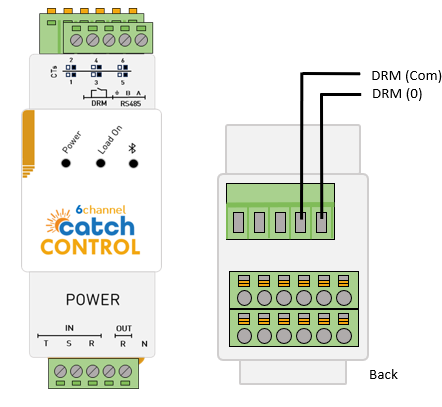
Our 6CH CATCH Control includes a DRM port (2 to 5 pin terminal interface) which can be used for Air-conditioner power management where they are DRM enabled and are equipped with DRM connection terminal’s. This will adjust the air-conditioner maximum power draw (typically increments of 0%, 50%, 60%, 75% or 100%).
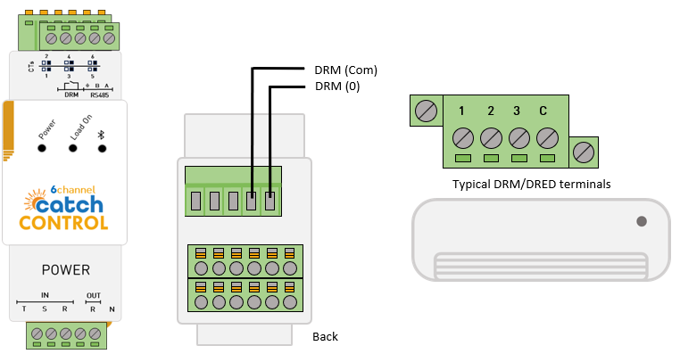
Connect the DRM output terminals from CATCH Control the the appropriate terminals on the Air Conditioner as per the below diagram. Refer to the relevant Air Conditioner manual to determine which terminal to connect to the achieve the desired results.
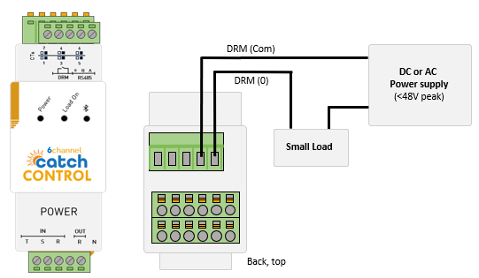
1.5.3 Direct control of a small loads via DRM port
The DRM port can be used to switch a small AC or DC load with ratings less than the absolute maximum specifications (as per 1.5.1)
- Never exceed the absolute maximum ratings of the solid state switch or damage will occur
The following diagram shows an indicative guide to connection.
1.5.4 Indirect control of a large loads via DRM port
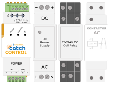
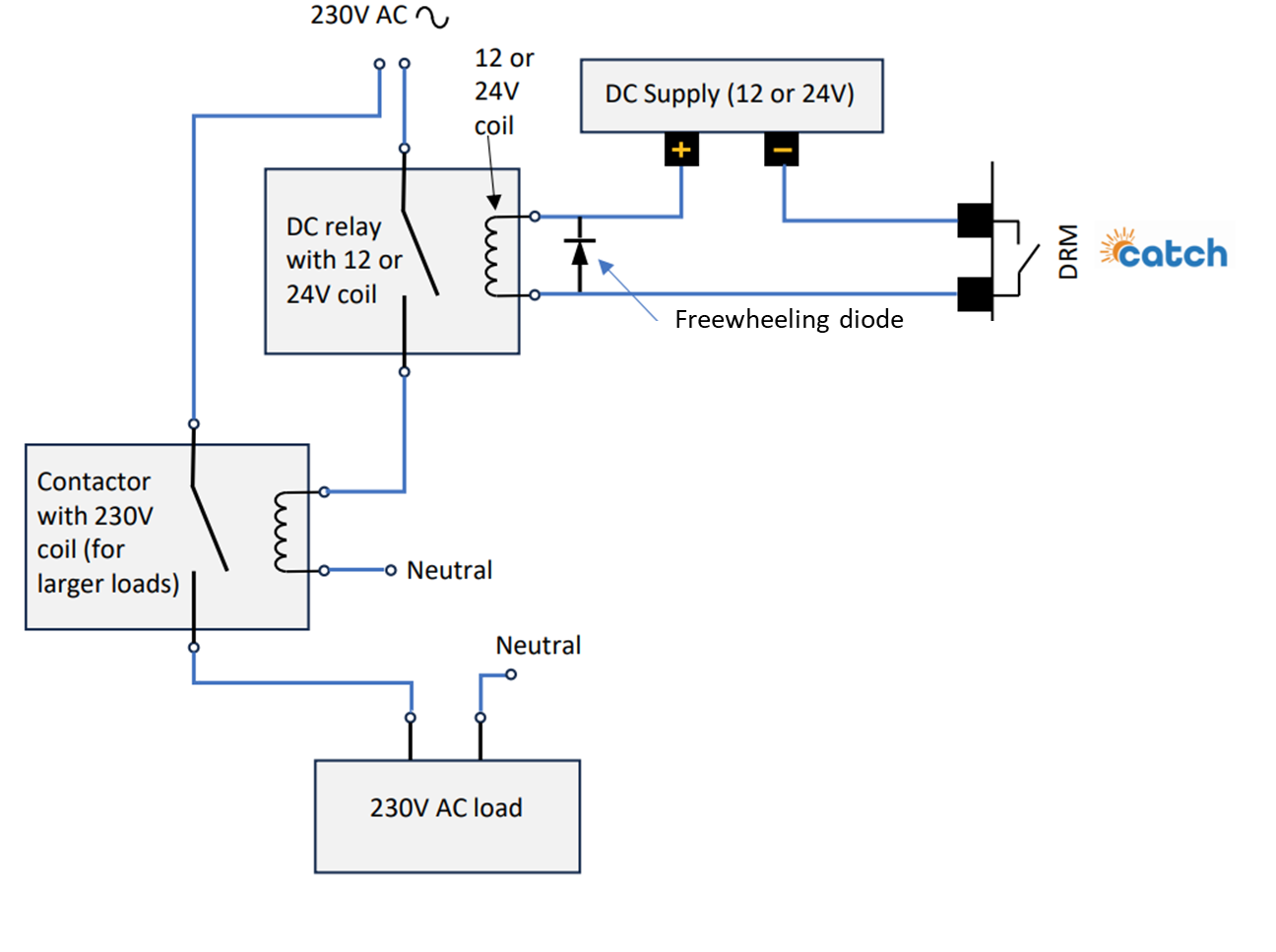
The DRM port can be used to switch larger loads via a DC Coil Relay, freewheeling diode and AC Contactor.
- Very important !! The freewheeling diode must be placed with the cathode to the positive input of the relay coil and the anode to the negative input of the coil or damage will occur
- Note: The key specifications for the free wheeling diode are as follows:
- Reverse Voltage: > 2x the DC supply voltage
- Diode forward current: > 3x relay on state coil current (or >= DRM contact current rating (400mA))
- Reverse current rating: < 1mA
- Diode Type: ‘Standard’ or ‘Schottky’ are suitable
- Forward Voltage: < 2V
- Example: Vishay – BAW27 (60V reverse, 600mA)
The following diagram shows an indicative guide to connection.
2. Initial commissioning
- Apply power to the CATCH Control.
- When power is applied the Power and Bluetooth LEDs will flash on and off for about 20sec, then just the power light will stay on.
- Open the Configurator app and connect via Bluetooth. Using the Wizard, follow these steps (or Watch the video here):
- Introduction and start up - initialisation of commissioning
- Connect - select the serial number of the device and connect
- Firmware update - ensure the latest firmware is installed and update
- Connect to WiFi - enter local wifi credentials and ensure wifi signal is a minimum of -60db
- Attach to site - create a site for the owner or search for existing site and attache device
- Inverter control - select the inverter brand and type. Refer to the relevant inverter commissioning guide for unique modbus settings.
- Channel set up - ensure CT and channels are connected and reading correctly. Name CT channels here.
- EDDE Control - enable EDDE control if you require inverter or battery control, backstop, flexible or static export management, EV or wholesale market control
- Export Control - Static, Dynamic and Backstop limits are set here. Begin by setting the inverter export limit to zero in the native inverter app and then, choose the appropriate export control method in EDDE (Backstop operates under the Dynamic mode). Press save. when complete.
- Enter the sites NMI number. If correct, the DNSP Identifier will be displayed.
- Enter the total solar size in Watts (defined as maximum inverter rating)
- Press save. You should see 4 green ticks in the status page indicating correct registration
- Save configuration - save your settings
2.1 CT configuration
Using the configurator in the previous step allows the Wizard to assist you with CT setup.
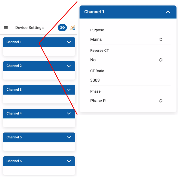
You can check or adjust the CT settings in Configurator in the Device settings page. Every CT needs to be allocated a Purpose and there are three purposes that can be used:
- MAINS: A Mains CT is one that is monitoring the export and import on the property
- SOLAR: A Solar CT is one that is monitor some form of solar.
- OTHER: These CT’s measuring generic loads such as hot water services, heating circuits, etc.
In each CT submenu you can define and check the following:
- Reverse CT: This is the same as switching the physical CT around in the switchboard. You wont need to change this. You and the CATCH support team can change this setting remotely which is very handy if you notice the CT was around the wrong way after you have left site.
- CT Ratio: Use the standard CATCH CT’s and leave this as 3003.
- Phase: The voltage phase this CT is mapped to. If you are on a split phase site you will need to remap CT 3 & 4 away from Phase S because phase S cannot be connected in a split phase configuration.
Expand each Channel section and confirm the CT settings are correct.
Remember, these are the default CT to Phase mapping configurations:
3. Testing the installation
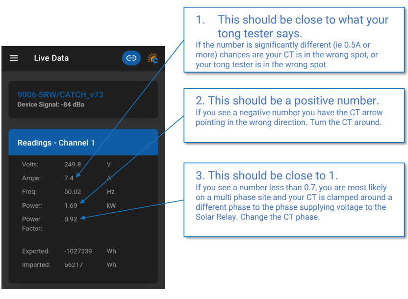
Once installed, powered up and updated check the readings are correct in Live Data found in the main menu.
The CATCH convention for power is as follows:
A POSITIVE power number is power being consumed (or imported) on the premises.
A NEGATIVE power number is power being produced (or exported) from the premises.
Keep your eye on the voltage measurement. If you don’t see it changing the live data screen may have stopped refreshing. It does this to conserve phone battery. To make it start refreshing again use the menu on the top left to navigate to a different screen, then come back to the Live Data page.
3.1 Test the Mains CT
This test allows you to conform the solar CT is reading correctly. Shutdown the solar and or battery and use your tong meter to measure a minimum of 2A on the Mains circuit.
- The current should match what you are seeing on your tong meter
- Power measurement should be Positive
- Power factor should be >0.7
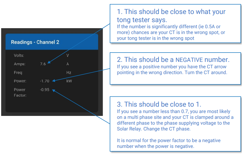
3.2 Test the Solar CT’s
This test allows you to conform the solar CT is reading correctly. Turn on the solar system (leave batteries turned off) and use your tong meter to measure a minimum of 2A on the Solar circuit.
- The current should match what you are seeing on your tong meter
- Power measurement should be Negative
- Power factor should be >0.7
The following provides advice on typical fault conditions:
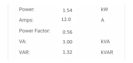
**Bad Connection:**If there is a bad connection on one or both CT wires you will get either ZERO or VERY HIGH readings for Amps.

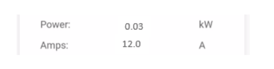
Current reading but no power: This typically means the CT needs to be remapped to a phase that has a voltage on it. You will get this type of problem in split or single-phase environments where not all voltage inputs are being used.
Low power factor: This typically means the CT is on the wrong phase and needs to be moved. This is only true if you have power above 500W. When there is little to no power, power factor will be low (almost zero), and this is normal. But if you have power above 500W and low power factor this is an indicator you have the CT on the wrong phase. You can either remap it in the configurator setup or physically move the CT.
3.3 Test the RS485 RTU connection
You will know if the RS485 RTU is or is not working because the inverter will have a fault code on it. This test allows you to confirm that the inverter and CATCH Control meter are communicating correctly.
- Make sure your inverter is on and configured for an energy meter
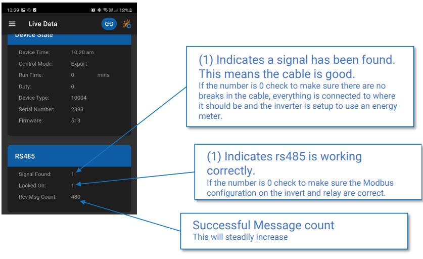
- Navigate to the Live data screen on the Configurator and select the RS485 section.
- Ensure Signal Found shows a connected 48 signal (indicated by “1”)
- Ensure Locked On shows a stable connection (indicated by “1”)
- Ensure Rcv Message Count is steadily growing as data flows (will steadily increase)
For information on Modbus TCP/Sunspec connections please refer the the inverter brand specific guide.
3.4 Testing the Load Contactor
- Navigate to Device Settings in the Main menu
- Expand System Override 1 and configure it as follows :
- Active Override YES
- Override Type TURN ON
- Start time 6.00am
- Stop time 6.00pm
- Hit the Save button
The Solar Relay Load On light should have turned on. If the Load On light didn’t turn on check the settings you used in Override 1.
- Make sure the time period suits your current time, and make sure you choose TURN ON.
- You should hear the contactor go “CLUNK”, and the contactor indicator light should be on.
If you didn’t get this, then check the following:
- Make sure the Active Out from the Relay is connected to either A1 OR A2 on the contactor
- Make sure that Neutral is connected to the other A1, A2 terminal (the one that Active Out is not connected to).
- Check to make sure an RCD has not tripped. If an RCD has tripped check to make sure your neutrals are as they should be. Remember the most common cause of an RCD tripping will be neutral return currents not passing through the RCD.
- Tong the load wire passing through the contactor, and make sure there is power flowing to the load.
Once you have confirmed correct operation, go back to System Override 1 and change them back to the defaults. You will set up custom Load Control settings at a later step.
3.4 Testing set up in the Monocle
The final testing step is to check the site looks correct in the Monocle app.
As part of the site creation process, an email with instructions has been created and sent to the customer. The customer will receive an access token required to register themselves as the owner of the site you have created.
- Open the Monocle app and log in
- If this is your very first Monocle site, the site should open as the default site. If you have multiple sites already, choose the site from the Site List by entering the address
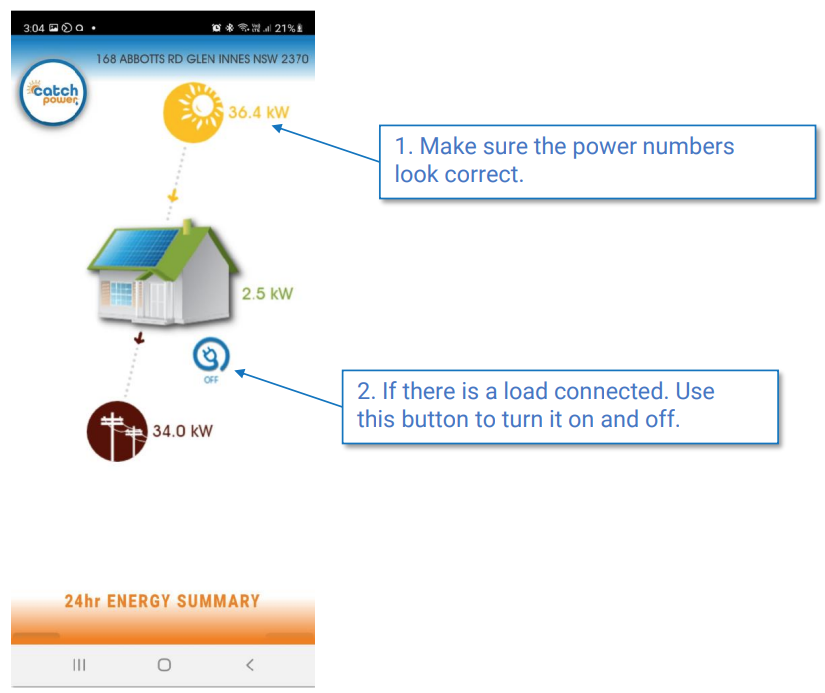
- Check that the production and consumption numbers appear correct
- If a load contactor is connected, test the function using the load control on/off icon
- If the site is participating in a Dynamic or Backstop exports program then “Derick the Dynamic Gateway” control icon should be present, letting you know the current site export limit
If all displays are correct, the site is correctly configured.
4.0 Setting up the Load controller
Use the Configurator to set up the CATCH Control to drive the contactor based on schedules or events. By default the device is setup to a common configuration used for controlling hot water loads in Queensland. Have a look at the settings and see if they suite your specific circumstance, if not then change them.
You can program and combine up to 4 different modes of operation, with each configuration active for a particular period in a 24hr window.
- Navigate to Device Settings from the main menu
- Choose the appropriate control mode to suit the owner needs:
- **Export Control :**turning on and off based on solar export levels. Good for Solar self consumption
- Voltage Control : turning on and off based on voltage levels. Good for trying to reduce voltage rise issues
- **Frequency Control :**turning on and off based on frequency. Good for use in a microgrid environment.
- Turn On/Off: Manual control of the contactor
- Top up: this one is a little tricky. Top up mode ensures a minimum amount of energy delivered to the load every 24hrs. Excellent for ensuring nobody runs out of
hot water.
4.1 Example load control set up
The following example describes a typical Hot Water Load control setup, using two overrides operating together.
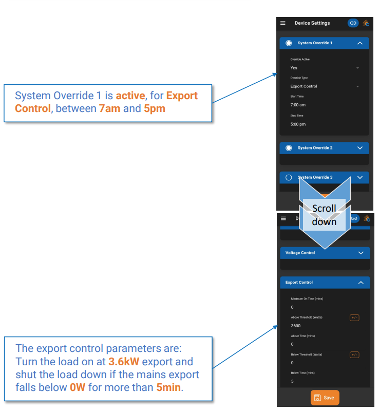
- Override 1 - Capturing exported production to trigger a hot water element and setting the element size
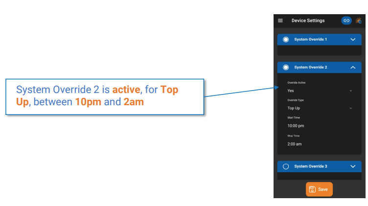
- Override 2 - Triggering a Top Up if the amount of energy delivered in Override 1 was not delivered
The goal of this configuration is firstly to turn on a 3.6kW element when >3.6kW of excess production is being exported, and turn off the contactor if <3.6kW is delivered for >5minutes. Override 1 defines the hours to look for excess (7am to 5pm), the element/excess size (3.6kW) and the time to shut off in excess power is not available (5minutes).
Secondly, we want a minimum of 4hrs of energy delivered to the load to ensure adequate heating. If the amount of energy delivered during the day is less than the 4 hours we have defined, the CATCH Control will make up the difference by turning the load on
at 10pm. If the amount of energy already delivered is greater than or equal to the 4 hours, nothing will happen at 10pm. The number of hours defined in Override 2 establishes this (between 10pm and 2am).
The hot water element will automatically turn off when it reaches normal temperature cut off thresholds.
Override 1
Override 2
5. Completion and support
The configuration and Monocle apps should now be operating correctly and the site is ready for use.
-
The Commissioner Wizard will notify you if things look abnormal.
-
Ensure you provide the Owners Guide to system owners so they understand how to adjust the site settings if required
-
Ensure you provide a link to the Wifi reconnection guide so owners can reconnect if wifi drops out.
-
To configure unique settings for load control, EVSE control or market price control please refer to our detailed service specific guides.
-
Owners written guide to the Monocle
Support
Please contact our tech support team on (02) 5700 5717 for assistance on set-up or commissioning.
CATCH Power
180 Dumaresq Street Glen Innes NSW 2370 Australia
Ph: +64 2 5700 5717